Cutting machines are mainly used in the metal and non-metal industries. Generally speaking, the classification of non-metallic industries is more detailed, such as water cutting machines and sawtooth cutting machines for cutting stones; laser cutting machines and blade cutting machines for cutting fabrics or plastics, and chemical fiber products; and plasma cutting for metal materials Cutting machine, zigzag cutting machine, flame cutting machine and so on.
At present, in the field of bar material cutting, mainly sawtooth type cutting machines are used. This type of cutting machine has advantages when cutting bar material with a diameter greater than 40 mm; in the field of bar material cutting with a diameter of less than 40 mm, the cutting method is not only sawing, There is also mechanical or hydraulic impact shearing.
In order to meet the requirements for rapid and precise cutting of slender bars, metal wires and profiles in production, a hydraulic impact bar rapid cutting machine is designed. This design specifically describes the design principles and corresponding hydraulic control principles of the three parts of the cutting machine’s hammer head, buffer and feeding system.
1. Design principle of cutting machine
A large amount of plastic work produced by a material under large deformation leads to a local temperature rise of the material. The local temperature rise further leads to the thermal softening of the material, resulting in greater deformation, which eventually leads to the destruction of the material. It is an important failure mode that often occurs in metal materials. The cutting machine is designed according to this basic principle, and its working process is as follows:
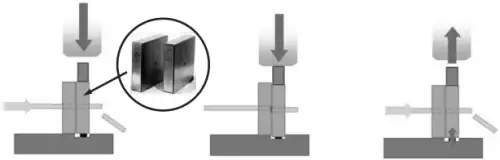
Step 1: The feeding system feeds the bar stock.
Step 2: the hammer head impacts the mold, the bar material is thermally softened and cut, and the bottom buffer mechanism absorbs the kinetic energy of the mold to stop it smoothly.
Step 3: The buffer mechanism ejects the mold and restores it to the initial position. The feeding system feeds again and continues to repeat the above steps.
2. Cutting machine system design

Machine Design. The cutting machine is mainly composed of a hammer head, a lubrication system, a buffer, a base, and a feeding system.
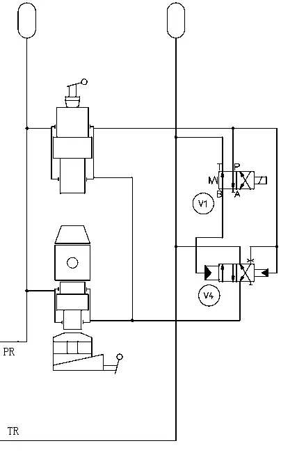
Hydraulic schematic
Hammerhead
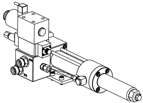
The hammer head is composed of a piston rod, a cylinder body, and a manual stroke adjustment device. The design of the hammerhead adopts a modular design method, combining various parts and standard parts to form a hammerhead system. It has the advantages of easy replacement and relative independence.
The piston rod material of the hammer head is CALMAX, the hardness is HRC54-56, and it has good toughness and impact resistance. As shown in the figure, the manual adjustment device for the stroke of the hammer head 1 is used to adjust the stroke of the hammer head piston rod to control the shear kinetic energy of the piston rod. When it is necessary to cut a bar with a smaller diameter, the stroke is reduced; when cutting a large-diameter bar, the stroke is increased.
Because the fall of the hammer head needs to quickly drain the hydraulic oil with resistance in the forward direction, a large flow directional valve is needed here, so a non-standard hydraulic directional valve V4 is designed, and its directional action is controlled by V1 It is a standard solenoid directional valve.
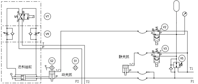
Schematic diagram of feeding system
The working process of the feeding system is as follows: First, adjust the specified stroke of the feeding cylinder. After loading the bar, move the clamp to tighten the bar and advance to the specified cutting length. The gripper is loosened and returned, the feeding is tightened again, and the feeding and cutting are reciprocated.
The displacement sensor is used to receive the position signal of the moving clamp to control the commutation of the feeding cylinder. The position of displacement sensor S1 is fixed, and the position of S2 is adjustable. The electromagnetic reversing valve V7 controls the feeding cylinder reversing, and the two-way flow control valve V9 is used to adjust the flow so that it is basically constant and is not affected by pressure and temperature. Electromagnetic directional valves V2 and V3 are used to control the clamping and loosening of dynamic and static gripping.
Buffer design and its working principle
The buffer consists of a buffer cylinder and an adjustable cushion. The adjustable cushion structure is mainly composed of a pressure plate, a polyurethane cushion, a rotation adjustment mechanism, a V-shaped wedge, and a bottom plate.
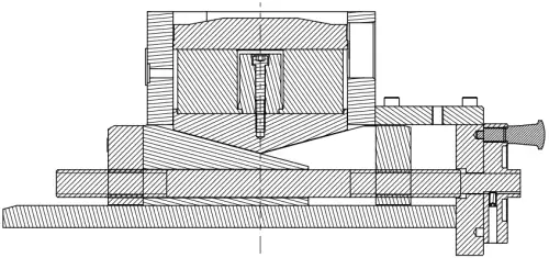
The buffer cylinder plays the role of restoring the initial position of the mold, but it can not withstand the huge impact force of the hammer head. Therefore, a buffer pad with adjustable support height is designed here.
The design stroke of the cylinder is 160 mm, and the maximum length of the feed is designed to be 150 mm. During the working process of the oil cylinder, the piston rod reciprocates frequently, which will produce wear and a lot of heat. Here, the sealing method of the piston rod and the cylinder block is composed of a 3-level sealing ring and two high-strength wear rings. In terms of heat dissipation, two 6-L accumulators are added to the P2 and T2 ports in the schematic diagram of the feeding system of Fig. 5, not only to dissipate heat and maintain pressure, but also to buffer the impact of the reciprocating movement of the piston rod.
3. END
A new design method of hydraulic impact bar cutting machine is proposed. The design mainly includes three parts: hammer head, buffer and feeding system. Through the actual cutting test, the number of bars with a length of 25 mm per minute is 150, and the length error is less than 0.05 mm. The design of impact cutter has enlightenment and reference significance to the field of cutting machine design.